SMath For Engineering Calculations - How to create interconnected calculations - Сообщения
I think both of these are very impressive and a good learning too. I am realizing now though what I need is probably just a simple beam program. If I could figure out how to incorporate a cantilever that would be good too. I realize though now that in practice when designing I most need a simple beam program. It is really all about speed and ease of use. It is cumbersome to have to input nodes at each point load, etc. I now realize if I get to a situation where I have continuous beams it is usually easier to use an FEM package that we already have. So now I have egg on my face as I was the one who suggested the FEM approach in the first place. Anyway, we are pretty busy at work but I'm going to try and see if I can finish up this function. I think this is ultimately the most difficult part. Most other engineering calculations are simply just following material codes and engineering principles.
My ability to create graphs is regrettably shameful...
Is it possible to add a graph of the moment, shear, deflection in my post #27 ?
Thanks
This may factor into "what is the best ways to format calculations" or maybe when should the recalculation be triggered (which I notice has improved)....
Simple Beam - Function.sm (70,36 КиБ) скачан 1224 раз(а).
WroteIs it possible to add a graph of the moment, shear, deflection in my post #27 ?
Yes. The functions defined in your sheet can directly be plotted using the built-in 2D plot region. It is sensible to define appropriate reference values for scaling, possibly the maximum absolute values. You probably need them anyways, so you might replace them in the denominators in the list of plot items.
BTW, do you trust the slope function (being all negative instead of changing sign at maximum y)?
beamplot.sm (80,65 КиБ) скачан 1138 раз(а).
ЦитатаBTW, do you trust the slope function (being all negative instead of changing sign at maximum y)?
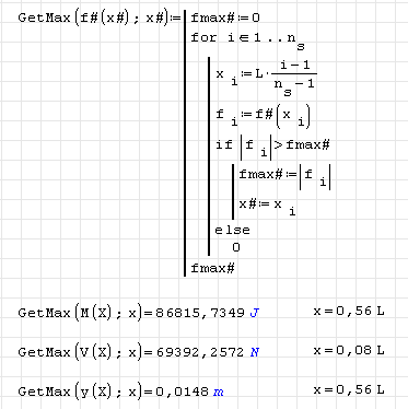
There are for sure a few things I need to change, I was getting tired. I need to figure out how to present the results. I want to return the left end and right end reactions as well as maximum shear, moment and deflection. I'd like to report their location as well but not exactly necessary.
Could you maybe try and explain how/why/what you did when setting up the plot? I don't quite understand. I see that I'm really looking at a fraction of the total shear/moment/deflection, I'm curios to know why you set it up like that? I suppose this is OK but again in practice you really don't need the diagrams, so maybe I am wasting time however... Is it possible to show the actual shear, moment and deflection?
In the function I posted do you see a good way or procedure to determine the location of maximum moment and deflection?
Thanks again!!
Wrote
Could you maybe try and explain how/why/what you did when setting up the plot? I don't quite understand. I see that I'm really looking at a fraction of the total shear/moment/deflection, I'm curios to know why you set it up like that? I suppose this is OK but again in practice you really don't need the diagrams, so maybe I am wasting time however... Is it possible to show the actual shear, moment and deflection?
In the function I posted do you see a good way or procedure to determine the location of maximum moment and deflection?
Even if you do not really need the diagrams, they just provide a visual feedback on how the function understood your input data.
The plot uses the following techniques:
- plotting multiple items using a list (system)
- x is scaled by L in order to give it the required dimension. x in the plot region has no dimension on it's own. Thus no matter how long the beam is, the plot will occupy the interval 0...1
- in order to cut off the plot outside 0...1 I used the function ltlt() from Davide's function's extensions plugin, which displays as a ternary relational operator. See the help snippet.
- In order to plot curves of different units and different order of magnitude in a single diagram (and again in order to avoid axis scaling) I divided the curves by some arbitrary representative value (taking the absolute value). Here the max absolute values would have to go.
- the y curve has a - sign because I like to see the sag going downwards.
as for the min/max finding: The only really robust way ist brute force, see attachment.
Your thoughts are aligned with mine and I'm very excited you brought this up. I will most likely continue down the path, whether others join in or not. Of course the most obvious problem I see will be codes as I am really only familiar with American codes. But I'm sure there will be much common ground.
So far, it has been important to me to establish a beam analyzer program as this is the most common tool and I realized a simple beam will probably suffice for now. I am interested in creating calculations that can be interconnected but also used as an individual sheet (therefore I would say that every thing should be a function as much as possible but this can be discussed in the "rules"). In some respects CSC World's Tedds for Word has done this as far as creating calculations in notebook style. Also a group effort has also been employed elsewhere as well see excelcalcs for example.
I agree with all your points and I was going to bring up that it would be nice to establish a template or scheme to follow (I have reserved some of these thoughts as I wanted to concentrate on the beam function).
Once I get the beam analyzer down, there is a small program that I'd like to create which can quickly compare joists by using a standard shear and moment diagram to your "new shear and moment diagram" in order to check existing joists (more to explain later). After this I think I'd like to start on masonry. I find there is a lack of tools to analyze partially grouted masonry walls loaded axially and out of plane. As well as shearwalls. After this maybe we try for a rigorous analysis of a biaxial bending and compressive concrete column. But I"m open for suggestions.
Martin -> Thank you for the GetMax formula and all the other information. Quick question why do I have to is the formula defined with a function and the variable x? Meaning, we input the variable x as part of the getmax function but yet we just redefine x in the function as x#=xi. So therefore why even input x into the function in the first place?... I was about to post this question but I think I see the answer...Is it so that the function returns the Maximum value as well as the corresponding location "x"? I also don't understand how x is then defined I mean I see x# is defined but then somehow the variable x is defined. Does the letter "x" do something special or am I missing something here? I have updated my function as well.
WroteMartin -> Thank you for the GetMax formula and all the other information. Quick question why do I have to is the formula defined with a function and the variable x? Meaning, we input the variable x as part of the getmax function but yet we just redefine x in the function as x#=xi. So therefore why even input x into the function in the first place?... I was about to post this question but I think I see the answer...Is it so that the function returns the Maximum value as well as the corresponding location "x"? I also don't understand how x is then defined I mean I see x# is defined but then somehow the variable x is defined. Does the letter "x" do something special or am I missing something here? I have updated my function as well.
All function defined using a statement block (line function) handle their argument calls by reference and not by value. Therefore, you can use the argument slots for input and output, as was done with the second argument. The actual argument in the call can be any variable name, defined or undefined. It is re-defined inside the function and indeed I did that in order to return the max value and the location.
Consider the function parameters being I/O channels from the calling context to the function. You even cound make use of the contents of x inside the function and then overwrite it with some output information.
Alternatively, you can return compound objects like matrices and lists, as you do in your beam function.
The first argument of the function GetMax() is the function to evaluate. In the call this argument is the function name with the appropriate number of arguments. These arguments are irrelevant but must be undefined.
Wrote
* it is useful to have an animator of the thread; viewing his contributions in the forum and his enthusiasm, I think that this animation could be successfully done by Dr Martin Kraska; of course if he accepts this;
* of course, I can accept also that the idea is not shared and that it is fond as better that everyone handle his problems by himself or in other circles than in this forum; the relative weak success of RFreund's idea till now I suppose is due also to the particular subject opened - that of continuous beams.
Ioan, thanks for your trust in that ma help in structuring the efforts could be useful. However, I am not really familiar with routine work of structural engineers along design codes. Perhaps Davide could be of more help, as he has much more insight into SMath Studio than me.
So far I did not really care the requirements but just jumped in when I saw a good opportunity to just give another example of using Maxima. I am not sure what an "animator" is expected to do. Writing something like the following?
Let me try to sum up what we have so far:
- Several structural engineers wishing to use SMath for standard calculations following different design codes.
- In mechanical engineering, there is software like MDesign or KissSoft for such tasks. Our students use it to design e.g. gear trains. Also, there are extensions for FEA software to evaluate the results according to codes like the FKM-Richtlinie, a german mechanical engineering code. All this stuff incorporates many man years of development and costs some money.
- We have the SMath sheet as the place where to put whatever input, processing and output.
- There are some results from a bottom-up approach, just like some ways to handle beams, a set of functions for generating profiles and computing their properties, some interactive features for making choices, setting values etc.
Now what I don't have:
- A clear idea of what the needs of the users are (workflow, data sources, formal requirements to results)
- An idea how to maintain an ambitious project with no ressources.
- Time to maintain another handbook (which I am convinced is the key to re-usability of whatever contribution)
What IMHO should be done:
- Find some place where to maintain the project (SMath wiki?) Someone has to start a page and fill it with the digest of this thread
- Identify typical workflows and possible support features
- Identify means to implement the features, including defining a data structure back bone (we would need objects with named attributes)
- Agree on some formal data representation
In particular, the last item is essential in order to collect different contributions and merge them into a powerful framework.
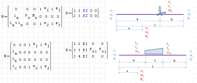
Anyways, whenever a concentrated load or a change in distributed load function is present, a node is required, thus your first case is represented by 2 elements and the second by three. In order to get some convenience, one could write sort of pre-processor, which set's up the beam elements and nodes according to the required load pattern.
The attached examples just show the required matrices, I'd not recommend to derive symbolic solutions.
You find the matrices under http://smath.info/cloud/worksheet/wwekLPpH
Wrote
I imagine that it would be possible an integration on intervals for the basic cases that I draw.
This is in respect with the intention to avoid an annoying situation when nodes are needed not only for section and end conditions change but also in dependence on loads position.
Yes, this is possible, but I'd prefer the basic element being as generic as possible. Perhaps I just can't see the problem with added nodes because I don't know the actual usage context. In FEA codes it is even common to have node divisions without any external reason, just because the internal interpolation functions are not available for postprocessing.
In that respect, a beam element with cubic ansatz and constant distributed load would be sufficient, if you use enough of them to represent your actual load distribution.
Wrote
I thought also on the solution on dividing in two separate segment division - one visible for the user and another one, internal for the program simplicity needs, but I'm convinced that it's possible also in a different way.
I can transport enough easily the efforts, but it is a little bit more complicated concerning the displacements.
I'm not to hurried, but I'd like to try to solve the subject like you have done for the trapezoidal load.
May be, it can be done, but I'd not recommend it. My fear is that the expressions might explode and drive smath to it's limits. I'd rather recommend writing a model generator based on some model description convention. One might wrap an FEA core into special case functions with whatever number of parameters.
What are you going to do with the special transfer functions? Solve for particular supports? Combine them into larger models? You could get that with FEA for free once the complete problem is described in terms of N and E matrices
I had thought about some sort of pre-processor as the main thing to make the FEM beam calculator useful is the ease of use. Meaning being able to specify the length and node restraint conditions for each span separate from the loading locations. So some sort of algorithm to automatically add notes at loading locations. However we also want to know the max/min shear, moment and deflection for each span (or atleast approximately, meaning we could subdivide the beam internally by a number of specified notes). However I then started to think, is this worth the effort???? Most beams will be simple span and for continuous concrete beams we have code approximations, for continuous steel beams I thought about using the three moment theorem and finally for any type of frame I would typically use a different software as you have many different load combinations, etc. However, there is one problem and that is many beams are overhang cantilever beams which I do not have answer for currently.
Having said that you guys have already put impressive effort into this and I would like to see it develop further.
I see that your major concern is about efficient min/max value detection and deformation. For the enhanced strain beam element (with internal degrees of freedom depending on the element loads) one could perhaps write some routine to get these values analytically and provide them as output values. Then typical structures could be handled by a relatively small number of elements.
BTW, the min/max search might be simplified if we restrict qI and qJ having the same sign. That would make Q having the extreme values at the nodes (no local extremum) and M having just one local extremum, if Q has a root.
To find the extrema of the displacement, one should examine the roots of the slope and the end points.
That might be better than brute force...
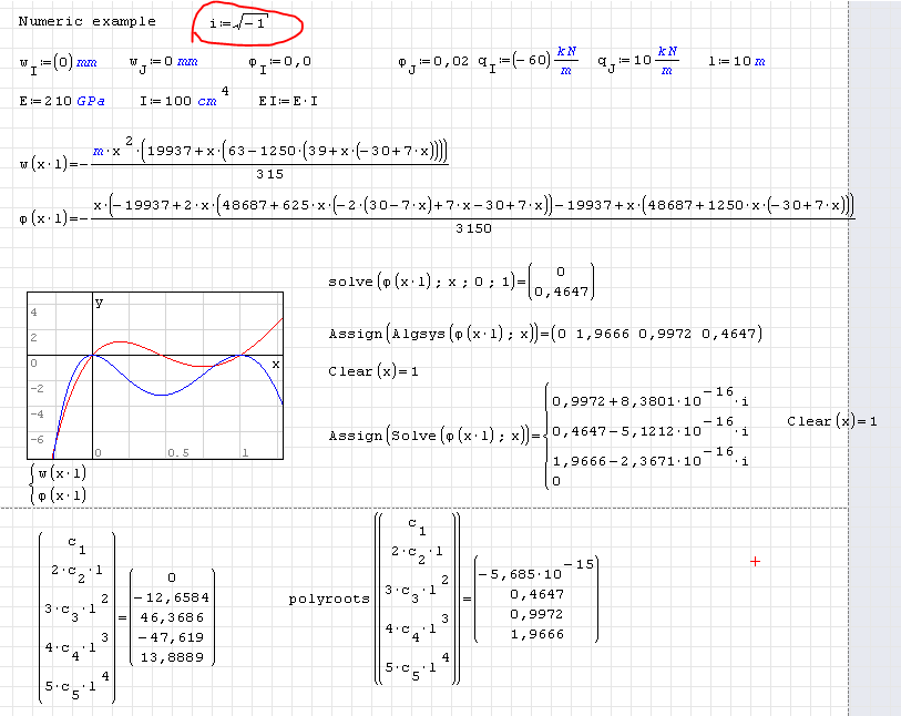
Edit: Here is the required math stuff for min/max detection of moment, shear and displacement. If you really expect this to be better than brute force, feel free to use it.
Balkenelement FEM Herleitung.sm (91,67 КиБ) скачан 1072 раз(а).
Wrote
I tried to use polyroot, without success.
Probably I'm wrong in a way.
I think the problem is in the insufficient robustness of the polyroots function. I don't know why for moderate coefficients and solutions this function has to crash.
Unfortunately, Solve() isn't reliable as well. Need to see if that is a maxima or translation issue.
That sounds for me like a pro for the brute force approach. If the smart approach is not reliable, then it is useless. One might end up with a nightmare of checks and workarounds.
Edit: The Solve function is not to blame. The problems resulted from i being re-defined in the upstream sheet, thus the complex part of the solution was displayed wronly. By assigning sqrt(-1) to i the problem is solved. I just ignored the survival rule "Do not change i". But the temptation is strong to use i in loop counters...
Anyways, the function Algsys() seems more appropriate for root finding of polynoms. It has a slightly different output format, which is more of a glitch than by design.

I will have to use it a bit, the preprocessor may still be a good idea, I'm just not sure the best way to go about it. I think it would be acceptable for the user to define the node location (or distance) and the restraint at that node in one input matrix. Then another input matrix for point loads, force and location. Then another for distributed loads. I'll see if I can give this some effort. But I do like the program you have, it is useful at this point.
As for the preprocessor, using the modeler region might be a good idea. One could define some basic objects like
- beam element (rectangle with the height indicating some cross section multiplier)
- symbols for different nodes (encastre, pin, symmetry (slope=0), articulation,
- arrow for point loads
- rectangle and triangle for distributed loads, stackable to represent arbitrary trapezoidal loads)
Then you could drag and drop symbols to build your model.
The modeler region allows to input numeric values for the size and position of the objects, thus you would not be restricted to screen resolution.
Based on the scetch, the function would produce the required matrices. There would be some problem dependent multipliers (units) for length, force, moment of inertia and distributed load.
The postprocessing could be made also in the modeler region, yet I don't know how to produce labels there. Andrey has demonstrated labels in his viewer examples but he did not share the method how to produce them.

ЦитатаPlease, could it be possible to introduce X-Y Plot Region format settings by program ? Thanks.
I'm busy now. I'll change the plug-in in the future and add new features.
- supports, forces and beams implemented
- vertical length of force arrow controls their value
- vertical length of beams controls their stiffness
- upward forces would require different symbol, no negative scaling.
- overlapping beams add their stiffness
- double click to specify locations and size of symbols (apparently anchored at center of bounding box
- No scaling of EI, F and lenght is done (I was too lazy for that)
Preprocessing and FEA solution are packed into functions and should be callable multiple times in a sheet (not tested).
Limitations: Modeller canvas has fixed origin, can only be scaled but not shifted interactively.
Yet it is fun to play around with the input.
prep.sm (121,52 КиБ) скачан 1215 раз(а).
- rotation constraint added
- more robust (node equivalence based on explicit tolerance)
- results graphics now Maxima-independent.
beam.sm (92,25 КиБ) скачан 1180 раз(а).

As minor thing, I suggest to use different colors to better distinguish loads and shear diagrams (f.e. green).
- Новые сообщения
- Нет новых сообщений